Embedded System for Hardware In the Loop (HIL) for generator

My thesis in the university were about design a physical module to make proofs with a generator in real time, but for explain this is some things to know after
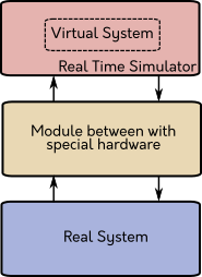
Real Time Simulation
Real time refers to a system that is executing a task in the correct time, there is no a complete definition but with a example can make the things easier, when you make a simulation of a system one of the parameters to define is the simulation time, suppose this time is 10 seconds and you push play to the simulation but depending on of the size of the simulation this can take more or less time but this is not real time simulation because for real time the time who trans cure while run the simulation and the simulated time is the same, there more concepts behind this but for this post is enough
Hardware In the loop
Imaging that you are making a real time simulation of a controller in your computer but the plant to control is real but with some special hardware you can apply the control to the plant, for example the plant is a DC motor, and the hardware who connect the computer and the motor is a micro controller (uC) like Arduino o ESP32, suppose than the uC have a transistor with this and a PWM signal can push energy in the motor and control the velocity and measure with a encoder, therefore the uC is a bridge between the DC motor and the computer, other supposition is that the uC is taking, measuring and sending the data with the same step time like the real time simulation because is important for all the functioning, to this fact than the controller or other system where is simulating in real time interacts with a physical system is called Hardware In the Loop (HIL)
Description
| For my thesis, the plant who need controlled was a generator, because this can be used to simulated classic generators or wind turbines with the objective the analysis of the micro grid’s behave with this type of generation, the idea is make some of this modules to have a complete micro grid. |
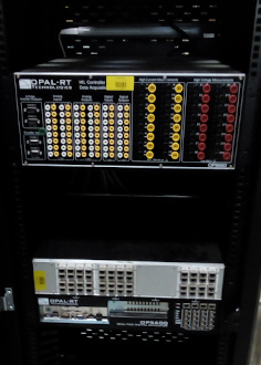
| The real time simulator was a OPAL-RT, because is so powerful and in the laboratory have one, this platform is like a normal computer but with more processors, hardware modules to connect and make HIL, modules with FPGA to make faster simulations and other tools to make awesome stuff, the OPAL-RT has a real time operating system based in RedHat but for programming a model can be used Simulink of MATLAB. |
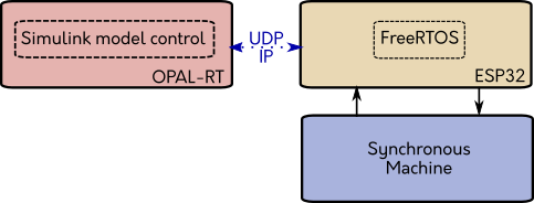
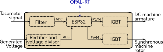
| OPAL-RT is so great, but in the laboratory don’t had modules to make HIL with the generator there is the first motivation to do the embedded system for my thesis, I have decisions to take, the first was the communication, I decided to use UDP-IP because this make the communication wireless and for the laboratory is more useful than other wired communication type, with this in my mind I selected the uC ESP32 because have WiFi, other decision to take is the programming of the uC I choose FreeRTOS to make a real time operating system and is compatible with the ESP32, is so much easier use this and secure that the step time is right, the diagram block of the module is |
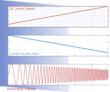
The generator is composed for a mechanical union of a synchronous and DC machine, the synchronous is the generator and the DC motor supply the energy, with this configuration can control the frequency and amplitude of generating signal give us more versatility for the proofs, the union is like see in the next picture
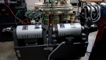
To change the frequency of the generated signal need to change the velocity of the DC motor, the amplitude change when the current of the rotor of the synchronous machine change
With the uC ESP32 I design a embedded system with power electronics and instrumentation, the instrumentation to measure the velocity in the DC is only a amplifiquer connected to the tachometer of the DC machine, to measure the amplitude of the generated voltage use a three phase rectifier and a voltage divisor for reduce the high voltage. For control the DC motor velocity use a IGBT connected in serie with the armature winding, the IGBT aperture is controller by the uC, and the rotor is conected to constant voltage, to control the current in the rotor of the synchronous machine is conected other IGBT in serie with the rotor of the sinchronous machine
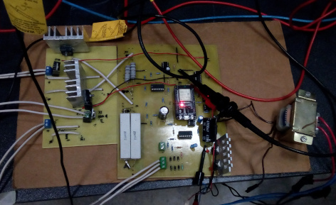
The embedded system when was finished
Finally charge a poportional controller in the OPAL-RT, through the embedded system can control the frequency and amplitude of the generated signal, the controller used was a PI
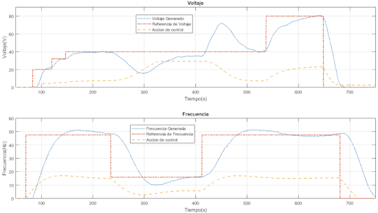
The generated voltage is the first plot and the second is the frequency, on the two figures the red signal is the reference, the yellow is the control output and the blue is the system output measure for the sensor.
| All the system works well, there are details that no is in this post but if you want to learn more about who it’s possible do the embedded system only you need read my thesis, but is in Spanish or can you contact me and can tell more for this post |
Comments